Learn About The Law
Get help with your legal needs
FindLaw’s Learn About the Law features thousands of informational articles to help you understand your options. And if you’re ready to hire an attorney, find one in your area who can help.
Current as of January 02, 2025 | Updated by Findlaw Staff
Department of the Army—Office of the Chief of Engineers
Preface
The recommended guidelines for the safety inspection of dams were prepared to outline principal factors to be weighed in the determination of existing or potential hazards and to define the scope of activities to be undertaken in the safety inspection of dams. The establishment of rigid criteria or standards is not intended. Safety must be evaluated in the light of peculiarities and local conditions at a particular dam and in recognition of the many factors involved, some of which may not be precisely known. This can only be done by competent, experienced engineering judgment, which the guidelines are intended to supplement and not supplant. The guidelines are intended to be flexible, and the proper flexibility must be achieved through the employment of experienced engineering personnel.
Conditions found during the investigation which do not meet guideline recommendations should be assessed by the investigator as to their import from the standpoint of the involved degree of risk. Many deviations will not compromise project safety and the investigator is expected to identify them in this manner if that is the case. Others will involve various degrees of risk, the proper evaluation of which will afford a basis for priority of subsequent attention and possible remedial action.
The guidelines present procedures for investigating and evaluating existing conditions for the purpose of identifying deficiencies and hazardous conditions. The two phases of investigation outlined in the guidelines are expected to accomplish only this and do not encompass in scope the engineering which will be required to perform the design studies for corrective modification work.
It is recognized that some States may have established or will adopt inspection criteria incongruous in some respects with these guidelines. In such instances assessments of project safety should recognize the State's requirements as well as guideline recommendations.
The guidelines were developed with the help of several Federal agencies and many State agencies, professional engineering organizations, and private engineers. In reviewing two drafts of the guidelines they have contributed many helpful suggestions. Their contributions are deeply appreciated and have made it possible to evolve a document representing a consensus of the engineering fraternity. As experience is gained with use of the guidelines, suggestions for future revisions will be generated. All such suggestions should be directed to the Chief of Engineers, U.S. Army, DAEN–CWE–D, Washington, D.C. 20314.
Recommended Guidelines for Safety Inspection of Dams
Table of Contents
Preface
CHAPTER 1—INTRODUCTION
Para.
1.1 Purpose.
1.2 Applicability.
1.3 Authority.
CHAPTER 2—GENERAL REQUIREMENTS
2.1 Classification of dams.
2.1.1 Size.
2.1.2 Hazard potential.
2.2 Selection of dams to be investigated.
2.3 Technical investigations.
2.4 Qualifications of investigators.
2.5 Reports.
CHAPTER 3—PHASE I INVESTIGATION
3.1 Purpose.
3.2 Scope.
3.3 Engineering data.
3.4 Field inspections.
3.5 Evaluation of hydraulic and hydrologic features.
3.5.1 Design data.
3.5.2 Experience data.
3.6 Evaluation of structural stability.
3.6.1 Design and construction data.
3.6.2 Operating records.
3.6.3 Post construction changes.
3.6.4 Seismic stability.
CHAPTER 4—PHASE II INVESTIGATION
4.1 Purpose.
4.2 Scope.
4.3 Hydraulic and hydrologic analysis.
4.3.1 Maximum water surface based on SDF peak inflow.
4.3.1.1 Peak for 100–year flood.
4.3.1.2 Peak for PMF or fraction thereof.
4.3.2 Maximum water surface based on SDF hydrograph.
4.3.3 Acceptable procedures.
4.3.4 Freeboard allowances.
4.4 Stability investigations.
4.4.1 Foundation and material investigations.
4.4.2 Stability assessment.
4.4.2.1 Seismic stability.
4.4.2.2 Clay shale foundation.
4.4.3 Embankment dams.
4.4.3.1 Liquefaction.
4.4.3.2 Shear failure.
4.4.3.3 Loading conditions.
4.4.3.4 Safety factors.
4.4.3.5 Seepage failure.
4.4.3.6 Seepage analyses.
4.4.4 Concrete dams and appurtenant structures.
4.4.4.1 Requirements for stability.
4.4.4.2 Loads.
4.4.4.3 Stresses.
4.4.4.4 Overturning.
4.4.4.5 Sliding.
4.4.4.5.1 Sliding resistance.
4.4.4.5.2 Downstream resistance.
4.4.4.5.3 Safety factor.
CHAPTER 5—REPORTS
5.1 General.
5.2 Preparation of report.
5.2.1 Phase I reports.
5.2.2 Phase II reports.
TABLES
Table
1 Size classification.
2 Hazard potential classification.
3 Hydrologic evaluation guidelines.
4 Factors of safety (embankment dams).
FIGURES
Fig.
1 Seismic zone map of contiguous States.
2 Seismic zone map of California, Nevada and Arizona.
3 Seismic zone map of Alaska.
4 Seismic zone map of Hawaii.
5 Design envelope for Case I (Table 4).
6 Design envelope for Cases II and III (Table 4).
APPENDIXES
Appendix I to App. D—Engineering data
Appendix II to App. D—Inspection items
Appendix III to App. D—Pub.L. 92–367
Chapter 1—Introduction
1.1. Purpose. This document provides recommended guidelines for the inspection and evaluation of dams to determine if they constitute hazards to human life or property.
1.2. Applicability. The procedures and guidelines outlined in this document apply to the inspection and evaluation of all dams as defined in the National Dam Inspection Act, Public Law 92–367. Included in this program are all artificial barriers together with appurtenant works which impound or divert water and which (1) are twenty-five feet or more in height or (2) have an impounding capacity of fifty acre-feet or more. Not included are barriers which are six feet or less in height, regardless of storage capacity, or barriers which have a storage capacity at maximum water storage elevation of fifteen acre-feet or less regardless of height.
1.3. Authority. The Dam Inspection Act, Public Law 92–367 (Appendix III), authorized the Secretary of the Army, through the Corps of Engineers, to initiate a program of safety inspection of dams throughout the United States. The Chief of Engineers issues these guidelines pursuant to that authority.
Chapter 2—General Requirements
2.1. Classification of dams. Dams should be classified in accordance with size and hazard potential in order to formulate a priority basis for selecting dams to be included in the inspection program and also to provide compatibility between guideline requirements and involved risks. When possible the initial classifications should be based upon information listed in the National Inventory of Dams with respect to size, impoundment capacity and hazard potential. It may be necessary to reclassify dams when additional information becomes available.
2.1.1. Size. The classification for size based on the height of the dam and storage capacity should be in accordance with Table 1. The height of the dam is established with respect to the maximum storage potential measured from the natural bed of the stream or watercourse at the downstream toe of the barrier, or if it is not across a stream or watercourse, the height from the lowest elevation of the outside limit of the barrier, to the maximum water storage elevation. For the purpose of determining project size, the maximum storage elevation may be considered equal to the top of dam elevation. Size classification may be determined by either storage or height, whichever gives the larger size category.
|
TABLE 1—SIZE CLASSIFICATION |
||
|---|---|---|
|
Impoundment |
||
|
Category |
Storage (ac-ft) |
Height (ft) |
|
Small |
<1,000 and ≥50 |
<40 and ≥25. |
|
Intermediate |
≥1,000 and <50,000 |
≥40 and <100. |
|
Large |
≥50,000 |
≥100. |
2.1.2. Hazard Potential. The classification for potential hazards should be in accordance with Table 2. The hazards pertain to potential loss of human life or property damage in the area downstream of the dam in event of failure or misoperation of the dam or appurtenant facilities. Dams conforming to criteria for the low hazard potential category generally will be located in rural or agricultural areas where failure may damage farm buildings, limited agricultural land, or township and country roads. Significant hazard potential category structures will be those located in predominantly rural or agricultural areas where failure may damage isolated homes, secondary highways or minor railroads or cause interruption of use or service of relatively important public utilities. Dams in the high hazard potential category will be those located where failure may cause serious damage to homes, extensive agricultural, industrial and commercial facilities, important public utilities, main highways, or railroads.
|
TABLE 2—HAZARD POTENTIAL CLASSIFICATION |
||
|---|---|---|
|
Category |
Loss of life (extent of development) |
Economic loss (extent of development) |
|
Low |
None expected (No permanent structures for human habitation) |
Minimal (Undeveloped to occasional structures or agriculture). |
|
Significant |
Few (No urban developments and no more than a small number of inhabitable structures) |
Appreciable (Notable agriculture, industry or structures). |
|
High |
More than few |
Excessive (Extensive community, industry or agriculture). |
2.2. Selection of dams to be investigated. The selection of dams to be investigated should be based upon an assessment of existing developments in flood hazard areas. Those dams possessing a hazard potential classified high or significant as indicated in Table 2 should be given first and second priorities, respectively, in the inspection program. Inspection priorities within each category may be developed from a consideration of factors such as size classification and age of the dam, the population size in the downstream flood area, and potential developments anticipated in flood hazard areas.
2.3. Technical Investigations. A detailed, systematic, technical inspection and evaluation should be made of each dam selected for investigation in which the hydraulic and hydrologic capabilities, structural stability and operational adequacy of project features are analyzed and evaluated to determine if the dam constitutes a danger to human life or property. The investigation should vary in scope and completeness depending upon the availability and suitability of engineering data, the validity of design assumptions and analyses and the condition of the dam. The minimum investigation will be designated Phase I, and an in-depth investigation designated Phase II should be made where deemed necessary. Phase I investigations should consist of a visual inspection of the dam, abutments and critical appurtenant structures, and a review of readily available engineering data. It is not intended to perform costly explorations or analyses during Phase I. Phase II investigations should consist of all additional engineering investigations and analyses found necessary by results of the Phase I investigation.
2.4. Qualifications of investigators. The technical investigations should be conducted under the direction of licensed professional engineers experienced in the investigation, design, construction and operation of dams, applying the disciplines of hydrologic, hydraulic, soils and structural engineering and engineering geology. All field inspections should be conducted by qualified engineers, engineering geologists and other specialists, including experts on mechanical and electrical operation of gates and controls, knowledgeable in the investigation, design, construction and operation of dams.
CHAPTER 3—PHASE I INVESTIGATION
3.1. Purpose. The primary purpose of the Phase I investigation program is to identify expeditiously those dams which may pose hazards to human life or property.
3.2. Scope. The Phase I investigation will develop an assessment of the general condition with respect to safety of the project based upon available data and a visual inspection, determine any need for emergency measures and conclude if additional studies, investigation and analyses are necessary and warranted. A review will be made of pertinent existing and available engineering data relative to the design, construction and operation of the dam and appurtenant structures, including electrical and mechanical operating equipment and measurements from inspection and performance instruments and devices; and a detailed systematic visual inspection will be performed of those features relating to the stability and operational adequacy of the project. Based upon findings of the review of engineering data and the visual inspection, an evaluation will be made of the general condition of the dam, including where possible the assessment of the hydraulic and hydrologic capabilities and the structural stability.
3.3. Engineering Data. To the extent feasible the engineering data listed in Appendix I relating to the design, construction and operation of the dam and appurtenant structures, should be collected from existing records and reviewed to aid in evaluating the adequacy of hydraulic and hydrologic capabilities and stability of the dam. Where the necessary engineering data are unavailable, inadequate or invalid, a listing should be made of those specific additional data deemed necessary by the engineer in charge of the investigation and included in the Phase I report.
3.4. Field inspections. The field inspection of the dam, appurtenant structures, reservoir area, and downstream channel in the vicinity of the dam should be conducted in a systematic manner to minimize the possibility of any significant feature being overlooked. A detailed checklist should be developed and followed for each dam inspected to document the examination of each significant structural and hydraulic feature including electrical and mechanical equipment for operation of the control facilities that affect the safety of the dam.
3.4.1. Particular attention should be given to detecting evidence of leakage, erosion, seepage, slope instability, undue settlement, displacement, tilting, cracking, deterioration, and improper functioning of drains and relief wells. The adequacy and quality of maintenance and operating procedures as they pertain to the safety of the dam and operation of the control facilities should also be assessed.
3.4.2. Photographs and drawings should be used freely to record conditions in order to minimize descriptions.
3.4.3. The field inspection should include appropriate features and items, including but not limited to those listed in Appendix II, which may influence the safety of the dam or indicate potential hazards to human life or property.
3.5. Evaluation of hydraulic and hydrologic Features.
3.5.1. Design data. Original hydraulic and hydrologic design assumptions obtained from the project records should be assessed to determine their acceptability in evaluating the safety of the dam. All constraints on water control such as blocked entrances, restrictions on operation of spillway and outlet gates, inadequate energy dissipators or restrictive channel conditions, significant reduction in reservoir capacity by sediment deposits and other factors should be considered in evaluating the validity of discharge ratings, storage capacity, hydrographs, routings and regulation plans. The discharge capacity and/or storage capacity should be capable of safely handling the recommended spillway design flood for the size and hazard potential classification of the dam as indicated in Table 3. The hydraulic and hydrologic determinations for design as obtained from project records will be acceptable if conventional techniques similar to the procedures outlined in paragraph 4.3. were used in obtaining the data. When the project design flood actually used exceeds the recommended spillway design flood, from Table 3, the project design flood will be acceptable in evaluating the safety of the dam.
|
TABLE 3—HYDROLOGIC EVALUATION GUIDELINES |
||
|---|---|---|
|
[Recommended spillway design floods] |
||
|
Hazard |
Size |
Spillway design flood (SDF)1 |
|
Low |
Small |
50 to 100-yr frequency. |
|
Intermediate |
100-yr to 1/2 PMF. |
|
|
Large |
1/2 PMF to PMF. |
|
|
Significant |
Small |
100-yr to 1/2 PMF. |
|
Intermediate |
1/2 PMF to PMF. |
|
|
Large |
PMF. |
|
|
High |
Small |
1/2 PMF to PMF. |
|
Intermediate |
PMF. |
|
|
Large |
PMF. |
1 The recommended design floods in this column represent the magnitude of the spillway design flood (SDF), which is intended to represent the largest flood that need be considered in the evaluation of a given project, regardless of whether a spillway is provided; i.e., a given project should be capable of safely passing the appropriate SDF. Where a range of SDF is indicated, the magnitude that most closely relates to the involved risk should be selected.
1000–yr=100–Year Exceedence Interval. The flood magnitude expected to be exceeded, on the average, of once in 100 years. It may also be expressed as an exceedence frequency with a one-percent chance of being exceeded in any given year.
PMF=Probable Maximum Flood. The flood that may be expected from the most severe combination of critical meteorologic and hydrologic conditions that are reasonably possible in the region. The PMF is derived from probable maximum precipitation (PMP), which information is generally available from the National Weather Service, NOAA. Most Federal agencies apply reduction factors to the PMP when appropriate. Reductions may be applied because rainfall isohyetals are unlikely to conform to the exact shape of the drainage basin and/or the storm is not likely to center exactly over the drainage basin. In some cases local topography will cause changes from the generalized PMP values, therefore it may be advisable to contact Federal construction agencies to obtain the prevailing practice in specific areas.
3.5.2. Experience data. In some cases where design data are lacking, an evaluation of overtopping potential may be based on watershed characteristics and rainfall and reservoir records. An estimate of the probable maximum flood may also be developed from a conservative, generalized comparison of the drainage area size and the magnitude of recently adopted probable maximum floods for damsites in comparable hydrologic regions. Where the review of such experience data indicates that the recommended spillway design flood would not cause overtopping additional hydraulic and hydrologic determinations will be unnecessary.
3.6. Evaluation of structural stability. The Phase I evaluations of structural adequacy of project features are expected to be based principally on existing conditions as revealed by the visual inspection, together with available design and construction information and records of performance. The objectives are to determine the existence of conditions which are hazardous, or which with time might develop into safety hazards, and to formulate recommendations pertaining to the need for any additional studies, investigations, or analyses. The results of this phase of the inspection must rely very substantially upon the experience and judgment of the inspecting engineer.
3.6.1. Design and construction data. The principal design assumptions and analyses obtained from the project records should be assessed. Original design and construction records should be used judiciously, recognizing the restricted applicability of such data as material strengths and permeabilities, geological factors and construction descriptions. Original stability studies and analyses should be acceptable if conventional techniques and procedures similar to those outlined in paragraph 4.4 were employed, provided that review of operational and performance data confirm that the original design assumptions were adequately conservative. The need for such analyses where either none exist or the originals are incomplete or unsatisfactory will be determined by the inspecting engineer based upon other factors such as condition of structures, prior maximum loadings and the hazard degree of the project. Design assumptions and analyses should include all applicable loads including earthquake and indicate the structure's capability to resist overturning, sliding and overstressing with adequate factors of safety. In general seepage and stability analyses comparable to the requirements of paragraph 4.4 should be on record for all dams in the high hazard category and large dams in the significant hazard category. This requirement for other dams will be subject to the opinion of the inspecting engineer.
3.6.2. Operating records. The performance of structures under prior maximum loading conditions should in some instances provide partial basis for stability evaluation. Satisfactory experience under loading conditions not expected to be exceeded in the future should generally be indicative of satisfactory stability, provided adverse changes in physical conditions have not occurred. Instrumentation observations of forces, pressures, loads, stresses, strains, displacements, deflections or other related conditions should also be utilized in the safety evaluation. Where such data indicate abnormal behavior, unsafe movement or deflections, or loadings which adversely affect the stability or functioning of the structure, prompt reporting of such circumstances is required without the delay for preparation of the official inspection report.
3.6.3. Post construction changes. Data should be collected on changes which have occurred since project construction that might influence the safety of the dam such as road cuts, quarries, mining and groundwater changes.
3.6.4. Seismic stability. An assessment should be made of the potential vulnerability of the dam to seismic events and a recommendation developed with regard to the need for additional seismic investigation. In general, projects located in Seismic Zones 0, 1 and 2 may be assumed to present no hazard from earthquake provided static stability conditions are satisfactory and conventional safety margins exist. Dams in Zones 3 and 4 should, as a minimum, have on record suitable analyses made by conventional equivalent static load methods. The seismic zones together with appropriate coefficients for use in such analyses are shown in Figures 1 through 4. Boundary lines are approximate and in the event of doubt about the proper zone, the higher zone should be used. All high hazard category dams in Zone 4 and high hazard dams of the hydraulic fill type in Zone 3 should have a stability assessment based upon knowledge of regional and local geology, engineering seismology, in situ properties of materials and appropriate dynamic analytical and testing procedures. The assessment should include the possibility of physical displacement of the structures due to movements along active faults. Departure from this general guidance should be made whenever in the judgment of the investigating engineer different seismic stability requirements are warranted because of local geological conditions or other reasons.
CHAPTER 4—PHASE II INVESTIGATION
4.1. Purpose. The Phase II investigation will be supplementary to Phase I and should be conducted when the results of the Phase I investigation indicate the need for additional in-depth studies, investigations or analyses.
4.2. Scope. The Phase II investigation should include all additional studies, investigations and analyses necessary to evaluate the safety of the dam. Included, as required, will be additional visual inspections, measurements, foundation exploration and testing, materials testing, hydraulic and hydrologic analysis and structural stability analyses.
4.3. Hydraulic and hydrologic analysis. Hydraulic and hydrologic capabilities should be determined using the following criteria and procedures. Depending on the project characteristics, either the spillway design flood peak inflow or the spillway design flood hydrograph should be the basis for determining the maximum water surface elevation and maximum outflow. If the operation or failure of upstream water control projects would have significant impact on peak flow or hydrograph analyses, the impact should be assessed.
4.3.1. Maximum water surface based on SDF peak inflow. When the total project discharge capability at maximum pool exceeds the peak inflow of the recommended SDF, and operational constraints would not prevent such a release at controlled projects, a reservoir routing is not required. The maximum discharge should be assumed equal to the peak inflow of the spillway design flood. Flood volume is not controlling in this situation and surcharge storage is either absent or is significant only to the extent that it provides the head necessary to develop the release capability required.
4.3.1.1. Peak for 100–year flood. When the 100–year flood is applicable under the provisions of Table 3 and data are available, the spillway design flood peak inflow may be determined by use of “A Uniform Technique for Determining Flood Frequencies,” Water Resources Council (WRC), Hydrology Committee, Bulletin 15, December 1967. Flow frequency information from regional analysis is generally preferred over single station results when available and appropriate. Rainfall-runoff techniques may be necessary when there are inadequate runoff data available to make a reasonable estimate of flow frequency.
4.3.1.2. Peak for PMF or fraction thereof. When either the Probable Maximum Flood peak or a fraction thereof is applicable under the provisions of Table 3, the unit hydrograph—infiltration loss technique is generally the most expeditious method of computing the spillway design flood peak for most projects. This technique is discussed in the following paragraph.
4.3.2. Maximum water surface based on SDF hydrograph. Both peak and volume are required in this analysis. Where surcharge storage is significant, or where there is insufficient discharge capability at maximum pool to pass the peak inflow of the SDF, considering all possible operational constraints, a flood hydrograph is required. When there are upstream hazard areas that would be imperiled by fast rising reservoirs levels, SDF hydrographs should be routed to ascertain available time for warning and escape. Determination of probable maximum precipitation or 100–year precipitation, which ever is applicable, and unit hydrographs or runoff models will be required, followed by the determination of the PMF or 100–year flood. Conservative loss rates (significantly reduced by antecedent rainfall conditions where appropriate) should be estimated for computing the rainfall excess to be utilized with unit hydrographs. Rainfall values are usually arranged with gradually ascending and descending rates with the maximum rate late in the storm. When applicable, conservatively high snowmelt runoff rates and appropriate releases from upstream projects should be assumed. The PMP may be obtained from National Weather Service (NWS) publications such as Hydrometeorological Report (HMR) 33. Special NWS publications for particular areas should be used when available. Rainfall for the 100–year frequency flood can be obtained from the NWS publication “Rainfall Frequency Atlas of the United States,” Technical Paper No. 40; Atlas 2, “Precipitation Frequency Atlas of Western United States;” or other NWS publications. The maximum water surface elevation and spillway design flood outflow are then determined by routing the inflow hydrograph through the reservoir surcharge storage, assuming a starting water surface at the bottom of surcharge storage, or lower when appropriate. For projects where the bottom of surcharge space is not distinct, or the flood control storage space (exclusive of surcharge) is appreciable, it may be appropriate to select starting water surface elevations below the top of the flood control storage for routings. Conservatively high starting levels should be estimated on the basis of hydrometeorological conditions reasonably characteristic for the region and flood release capability of the project. Necessary adjustment of reservoir storage capacity due to existing or future sediment or other encroachment may be approximated when accurate determination of deposition is not practicable.
4.3.3. Acceptable procedures. Techniques for performing hydraulic and hydrologic analyses are generally available from publications prepared by Federal agencies involved in water resources development or textbooks written by the academic community. Some of these procedures are rather sophisticated and require expensive computational equipment and large data banks. While results of such procedures are generally more reliable than simplified methods, their use is generally not warranted in studies connected with this program unless they can be performed quickly and inexpensively. There may be situations where the more complex techniques have to be employed to obtain reliable results; however, these cases will be exceptions rather than the rule. Whenever the acceptability of procedures is in question, the advice of competent experts should be sought. Such expertise is generally available in the Corps of Engineers, Bureau of Reclamation and Soil Conservation Service. Many other agencies, educational facilities and private consultants can also provide expert advice. Regardless of where such expertise is based, the qualification of those individuals offering to provide it should be carefully examined and evaluated.
4.3.4. Freeboard allowances. Guidelines on specific minimum freeboard allowances are not considered appropriate because of the many factors involved in such determinations. The investigator will have to assess the critical parameters for each project and develop its minimum requirement. Many projects are reasonably safe without freeboard allowance because they are designed for overtopping, or other factors minimize possible overtopping. Conversely, freeboard allowances of several feet may be necessary to provide a safe condition. Parameters that should be considered include the duration of high water levels in the reservoir during the design flood; the effective wind fetch and reservoir depth available to support wave generation; the probability of high wind speed occurring from a critical direction; the potential wave runup on the dam based on roughness and slope; and the ability of the dam to resist erosion from overtopping waves.
4.4 Stability investigations. The Phase II stability investigations should be compatible with the guidelines of this paragraph.
4.4.1 Foundation and material investigations. The scope of the foundation and materials investigation should be limited to obtaining the information required to analyze the structural stability and to investigate any suspected condition which would adversely affect the safety of the dam. Such investigations may include borings to obtain concrete, embankment, soil foundation, and bedrock samples; testing specimens from these samples to determine the strength and elastic parameters of the materials, including the soft seams, joints, fault gouge and expansive clays or other critical materials in the foundation; determining the character of the bedrock including joints, bedding planes, fractures, faults, voids and caverns, and other geological irregularities; and installing instruments for determining movements, strains, suspected excessive internal seepage pressures, seepage gradients and uplift forces. Special investigations may be necessary where suspect rock types such as limestone, gypsum, salt, basalt, claystone, shales or others are involved in foundations or abutments in order to determine the extent of cavities, piping or other deficiencies in the rock foundation. A concrete core drilling program should be undertaken only when the existence of significant structural cracks is suspected or the general qualitative condition of the concrete is in doubt. The tests of materials will be necessary only where such data are lacking or are outdated.
4.4.2. Stability assessment. Stability assessments should utilize in situ properties of the structure and its foundation and pertinent geologic information. Geologic information that should be considered includes groundwater and seepage conditions; lithology, stratigraphy, and geologic details disclosed by borings, “as-built” records, and geologic interpretation; maximum past overburden at site as deduced from geologic evidence; bedding, folding and faulting; joints and joint systems; weathering; slickensides, and field evidence relating to slides, faults, movements and earthquake activity. Foundations may present problems where they contain adversely oriented joints, slickensides or fissured material, faults, seams of soft materials, or weak layers. Such defects and excess pore water pressures may contribute to instability. Special tests may be necessary to determine physical properties of particular materials. The results of stability analyses afford a means of evaluating the structure's existing resistance to failure and also the effects of any proposed modifications. Results of stability analyses should be reviewed for compatibility with performance experience when possible.
4.4.2.1. Seismic stability. The inertial forces for use in the conventional equivalent static force method of analysis should be obtained by multiplying the weight by the seismic coefficient and should be applied as a horizontal force at the center of gravity of the section or element. The seismic coefficients suggested for use with such analyses are listed in Figures 1 through 4. Seismic stability investigations for all high hazard category dams located in Seismic Zone 4 and high hazard dams of the hydraulic fill type in Zone 3 should include suitable dynamic procedures and analyses. Dynamic analyses for other dams and higher seismic coefficients are appropriate if in the judgment of the investigating engineer they are warranted because of proximity to active faults or other reasons. Seismic stability investigations should utilize “state-of-the-art” procedures involving seismological and geological studies to establish earthquake parameters for use in dynamic stability analyses and, where appropriate, the dynamic testing of materials. Stability analyses may be based upon either time-history or response spectra techniques. The results of dynamic analyses should be assessed on the basis of whether or not the dam would have sufficient residual integrity to retain the reservoir during and after the greatest or most adverse earthquake which might occur near the project location.
4.4.2.2. Clay shale foundation. Clay shale is a highly overconsolidated sedimentary rock comprised predominantly of clay minerals, with little or no cementation. Foundations of clay shales require special measures in stability investigations. Clay shales, particularly those containing montmorillonite, may be highly susceptible to expansion and consequent loss of strength upon unloading. The shear strength and the resistance to deformation of clay shales may be quite low and high pore water pressures may develop under increase in load. The presence of slickensides in clay shales is usually an indication of low shear strength. Prediction of field behavior of clay shales should not be based solely on results of conventional laboratory tests since they may be misleading. The use of peak shear strengths for clay shales in stability analyses may be unconservative because of nonuniform stress distribution and possible progressive failures. Thus the available shear resistance may be less than if the peak shear strength were mobilized simultaneously along the entire failure surface. In such cases, either greater safety factors or residual shear strength should be used.
4.4.3. Embankment dams.
4.4.3.1. Liquefaction. The phenomenon of liquefaction of loose, saturated sands and silts may occur when such materials are subjected to shear deformation or earthquake shocks. The possibility of liquefaction must presently be evaluated on the basis of empirical knowledge supplemented by special laboratory tests and engineering judgment. The possibility of liquefaction in sands diminishes as the relative density increases above approximately 70 percent. Hydraulic fill dams in Seismic Zones 3 and 4 should receive particular attention since such dams are susceptible to liquefaction under earthquake shocks.
4.4.3.2. Shear failure. Shear failure is one in which a portion of an embankment or of an embankment and foundation moves by sliding or rotating relative to the remainder of the mass. It is conventionally represented as occurring along a surface and is so assumed in stability analyses, although shearing may occur in a zone of substantial thickness. The circular arc or the sliding wedge method of analyzing stability, as pertinent, should be used. The circular arc method is generally applicable to essentially homogeneous embankments and to soil foundations consisting of thick deposits of fine-grained soil containing no layers significantly weaker than other strata in the foundation. The wedge method is generally applicable to rockfill dams and to earth dams on foundations containing weak layers. Other methods of analysis such as those employing complex shear surfaces may be appropriate depending on the soil and rock in the dam and foundation. Such methods should be in reputable usage in the engineering profession.
4.4.3.3. Loading conditions. The loading conditions for which the embankment structures should be investigated are (I) Sudden drawdown from spillway crest elevation or top of gates, (II) Partial pool, (III) Steady state seepage from spillway crest elevation or top of gate elevation, and (IV) Earthquake. Cases I and II apply to upstream slopes only; slopes; and Case IV applies to both upstream and downstream Case III applies to downstream slopes. A summary of suggested strengths and safety factors are shown in Table 4.
|
TABLE 4—FACTORS OF SAFETY1 |
||||
|---|---|---|---|---|
|
Case and loading condition |
Factor of safety |
Shear2 strength |
Remarks |
|
|
I |
Sudden drawdown from spillway crest or top of gates to minimum drawdown elevation |
3 1.2 |
Minimum composite of R and S shear strengths. See Figure 5. |
Within the drawdown zone submerged unit weights of materials are used for computing forces resisting sliding and saturated unit weights are used for computing forces contributing to sliding. |
|
II |
Partial pool with assumed horizontal steady seepage saturation |
1.5 |
R+S/2 for R<S |
Composite intermediate envelope of R and S shear strengths. See Figure 6. |
|
S for R>S |
||||
|
III |
Steady seepage from spillway crest or top of gates with Kh/Kv=9 assumed4 |
1.5 |
Same as Case II |
|
|
IV |
Earthquake (Cases II and III with seismic loading) |
1.0 |
(5) |
See Figures 1 through 4 for Seismic Coefficients. |
1 Not applicable to embankments on clay shale foundation. Experience has indicated special problems in determination of design shear strengths for clay shale foundations and acceptable safety factors should be compatible with the confidence level in shear strength assumptions.
2 Other strength assumptions may be used if in common usage in the engineering profession.
3 The safety factor should not be less than 1.5 when drawdown rate and pore water pressure developed from flow nets are used in stability analyses.
4 Kh/Kv is the ratio of horizontal to vertical permeability. A minimum of 9 is suggested for use in compacted embankments and alluvial sediments.
5 Use shear strength for case analyzed without earthquake. It is not necessary to analyze sudden drawdown for earthquake loading. Shear strength tests are classified according to the controlled drainage conditions maintained during the test. R tests are those in which specimen drainage is allowed during consolidation (or swelling) under initial stress conditions, but specimen drainage is not allowed during application of shearing stresses. S tests allow full drainage during initial stress application and shearing is at a slow rate so that complete specimen drainage is permitted during the complete test.
4.4.3.4. Safety factors. Safety factors for embankment dam stability studies should be based on the ratio of available shear strength to developed shear strength, SD:
|
SD = |
(C/F.S.)+ |
(&b.sigma; tan &b.Phi;/F.S.) |
(1) |
Where:
C = Cohesion
φ = Angle of internal friction
σ = Normal stress
The factors of safety listed in Table 4 are recommended as minimum acceptable. Final accepted factors of safety should depend upon the degree of confidence the investigating engineer has in the engineering data available to him. The consequences of a failure with respect to human life and property damage are important considerations in establishing factors of safety for specific investigations.
4.4.3.5. Seepage failure. A critical uncontrolled underseepage or through seepage condition that develops during a rising pool can quickly reduce a structure which was stable under previous conditions, to a total structural failure. The visually confirmed seepage conditions to be avoided are (1) the exit of the phreatic surface on the downstream slope of the dam and (2) development of hydrostatic heads sufficient to create in the area downstream of the dam sand boils that erode materials by the phenomenon known as “piping” and (3) localized concentrations of seepage along conduits or through pervious zones. The dams most susceptible to seepage problems are those built of or on pervious materials of uniform fine particle size, with no provisions for an internal drainage zone and/or no underseepage controls.
4.4.3.6. Seepage analyses. Review and modifications to original seepage design analyses should consider conditions observed in the field inspection and piezometer instrumentation. A seepage analysis should consider the permeability ratios resulting from natural deposition and from compaction placement of materials with appropriate variation between horizontal and vertical permeability. An underseepage analysis of the embankment should provide a critical gradient factor of safety for the maximum head condition of not less than 1.5 in the area downstream of the embankment.
|
F.S = |
(ic/i= |
(Hc/Db/H/Db)= |
Db ((&b.gamma;m-&b.gamma;w)/H&b.gamma;w) |
(2) |
Where:
ic = Critical gradient
i = Design gradient
H = Uplift head at downstream toe of dam measured above tailwater
Hc = The critical uplift
Db = The thickness of the top impervious blanket at the downstream toe of the dam
γm = The estimated saturated unit weight of the material in the top impervious blanket
γw = The unit weight of water
Where a factor of safety less than 1.5 is obtained the provision of an underseepage control system is indicated. The factor of safety of 1.5 is a recommended minimum and may be adjusted by the responsible engineer based on the competence of the engineering data.
4.4.4. Concrete dams and appurtenant structures.
4.4.4.1. Requirements for stability. Concrete dams and structures appurtenant to embankment dams should be capable of resisting overturning, sliding and overstressing with adequate factors of safety for normal and maximum loading conditions.
4.4.4.2. Loads. Loadings to be considered in stability analyses include the water load on the upstream face of the dam; the weight of the structure; internal hydrostatic pressures (uplift) within the body of the dam, at the base of the dam and within the foundation; earth and silt loads; ice pressure, seismic and thermal loads, and other loads as applicable. Where tailwater or backwater exists on the downstream side of the structure it should be considered, and assumed uplift pressures should be compatible with drainage provisions and uplift measurements if available. Where applicable, ice pressure should be applied to the contact surface of the structure of normal pool elevation. A unit pressure of not more than 5,000 pounds per square foot should be used. Normally, ice thickness should not be assumed greater than two feet. Earthquake forces should consist of the inertial forces due to the horizontal acceleration of the dam itself and hydrodynamic forces resulting from the reaction of the reservoir water against the structure. Dynamic water pressures for use in a conventional methods of analysis may be computed by means of the “Westergaard Formula” using the parabolic approximation (H.M. Westergaard, “Water Pressures on Dams During Earthquakes,” Trans., ASCE, Vol 98, 1933, pages 418–433), or similar method.
4.4.4.3. Stresses. The analysis of concrete stresses should be based on in situ properties of the concrete and foundation. Computed maximum compressive stresses for normal operating conditions in the order of 1/3 or less of in situ strengths should be satisfactory. Tensile stresses in unreinforced concrete should be acceptable only in locations where cracks will not adversely affect the overall performance and stability of the structure. Foundation stresses should be such as to provide adequate safety against failure of the foundation material under all loading conditions.
4.4.4.4. Overturning. A gravity structure should be capable of resisting all overturning forces. It can be considered safe against overturning if the resultant of all combinations of horizontal and vertical forces, excluding earthquake forces, acting above any horizontal plane through the structure or at its base is located within the middle third of the section. When earthquake is included the resultant should fall within the limits of the plane or base, and foundation pressures must be acceptable. When these requirements for location of the resultant are not satisfied the investigating engineer should assess the importance to stability of the deviations.
4.4.4.5. Sliding. Sliding of concrete gravity structures and of abutment and foundation rock masses for all types of concrete dams should be evaluated by the shear-friction resistance concept. The available sliding resistance is compared with the driving force which tends to induce sliding to arrive at a sliding stability safety factor. The investigation should be made along all potential sliding paths. The critical path is that plane or combination of planes which offers the least resistance.
4.4.4.5.1. Sliding resistance. Sliding resistance is a function of the unit shearing strength at no normal load (cohesion) and the angle of friction on a potential failure surface. It is determined by computing the maximum horizontal driving force which could be resisted along the sliding path under investigation. The following general formula is obtained from the principles of statics and may be derived by resolving forces parallel and perpendicular to the sliding plane:
|
RR= |
V tan (&b.Phi; + &b.alpha;) + |
(cA)/cos &b.alpha;(1-tan &b.Phi; tan &b.alpha;)) |
(3) |
Where:
RR = Sliding Resistance (maximum horizontal driving force which can be resisted by the critical path)
φ = Angle of internal friction of foundation material or, where applicable, angle of sliding friction
V = Summation of vertical forces (including uplift)
c = Unit shearing strength at zero normal loading along potential failure plane
A = Area of potential failure plane developing unit shear strength “c”
α = Angle between inclined plane and horizontal (positive for uphill sliding)
For sliding downhill the angle α is negative and Equation (1) becomes:
|
RR=V tan (&b.Phi; - &b.alpha;) + |
(cA)/(cos &b.alpha;1+tan &b.Phi; tan &b.alpha;) |
(4) |
When the plane of investigation is horizontal, and the angle α is zero and Equation (1) reduced to the following:
|
RR=V tan &b.Phi; + cA |
(5) |
4.4.4.5.2. Downstream resistance. When the base of a concrete structure is embedded in rock or the potential failure plane lies below the base, the passive resistance of the downstream layer of rock may sometimes be utilized for sliding resistance. Rock that may be subjected to high velocity water scouring should not be used. The magnitude of the downstream resistance is the lesser of (a) the shearing resistance along the continuation of the potential sliding plane until it daylights or (b) the resistance available from the downstream rock wedge along an inclined plane. The theoretical resistance offered by the passive wedge can be computed by a formula equivalent to formula (3):
|
Pp = W tan (&b.Phi; + &b.alpha;) |
(cA)/(cos &b.alpha; (I-tan &b.Phi; tan &b.alpha;)) |
(6) |
Where:
PP = Passive resistance of rock wedge
W = Weight (buoyant weight if applicable) of downstream rock wedge above inclined plane of resistance, plus any superimposed loads
φ = Angle of internal friction or, if applicable, angle of sliding friction
α = Angle between inclined failure plane and horizontal
c = Unit shearing strength at zero normal load along failure plane
A = Area of inclined plane of resistance
When considering cross-bed shear through a relatively shallow, competent rock strut, without adverse jointing or faulting, W and α may be taken at zero and 45°, respectively, and an estimate of passive wedge resistance per unit width obtained by the following equation:
|
Pp = 2cD |
(7) |
Where:
D = Thickness of the rock strut
4.4.4.5.3. Safety factor. The shear-friction safety factor is obtained by dividing the resistance RR by H, the summation of horizontal service loads to be applied to the structure:
|
Ss-f = |
(RR)/(H) |
(8) |
When the downstream passive wedge contributes to the sliding resistance, the shear friction safety factor formula becomes:
|
Ss-f = |
(RR+PP)/(H) |
(9) |
The above direct superimposition of passive wedge resistance is valid only if shearing rigidities of the foundation components are similar. Also, the compressive strength and buckling resistance of the downstream rock layer must be sufficient to develop the wedge resistance. For example, a foundation with closely spaced, near horizontal, relatively weak seams might not contain sufficient buckling strength to develop the magnitude of wedge resistance computed from the cross-bed shear strength. In this case wedge resistance should not be assumed without resorting to special treatment (such as installing foundation anchors). Computed sliding safety factors approximating 3 or more for all loading conditions without earthquake, and 1.5 including earthquake, should indicate satisfactory stability, depending upon the reliability of the strength parameters used in the analyses. In some cases when the results of comprehensive foundation studies are available, smaller safety factors may be acceptable. The selection of shear strength parameters should be fully substantiated. The bases for any assumptions; the results of applicable testing, studies and investigations; and all pre-existing, pertinent data should be reported and evaluated.
CHAPTER 5—REPORTS
5.1. General. This chapter outlines the procedures for reporting the results of the technical investigations. Hazardous conditions should be reported immediately upon detection to the owner of the dam, the Governor of the State in which the dam is located and the appropriate regulatory agency without delay for preparation of the formal report.
5.2. Preparation of report. A formal report should be prepared for each dam investigated for submission to the regulatory agency and the owner of the dam. Each report should contain the information indicated in the following paragraphs. The signature and registration identification of the professional engineer who directed the investigation and who was responsible for evaluation of the dam should be included in the report.
5.2.1. Phase I reports. Phase I reports should contain the following information:
5.2.1.1. Description of dam including regional vicinity map showing location and plans, elevations and sections showing the essential project features and the size and hazard potential classifications.
5.2.1.2. Summary of existing engineering data, including geologic maps and information.
5.2.1.3. Results of the visual inspection of each project feature including photographs and drawings to minimize descriptions.
5.2.1.4. Evaluation of operational adequacy of the reservoir regulation plan and maintenance of the dam and operating facilities and features that pertain to the safety of the dam.
5.2.1.5. Description of any warning system in effect.
5.2.1.6. Evaluation of the hydraulic and hydrologic assumptions and structural stability.
5.2.1.7. An assessment of the general condition of the dam with respect to safety based upon the findings of the visual inspection and review of engineering data. Where data on the original design indicate significant departure from or non-conformance with guidelines contained herein, the engineer-in-charge of the investigation will give his opinion of the significance, with regard to safety, of such factors. Any additional studies, investigations and analyses considered essential to assessment of the safety of the dam should be listed, together with an opinion about the urgency of such additional work.
5.2.1.8. Indicate alternative possible remedial measures or revisions in operating and maintenance procedures which may (subject to further evaluation) correct deficiencies and hazardous conditions found during the investigation.
5.2.2. Phase II Reports. Phase II reports should describe the detailed investigations and should supplement Phase I reports. They should contain the following information:
5.2.2.1. Summary of additional engineering data obtained to determine the hydraulic and hydrologic capabilities and/or structural stability.
5.2.2.2. Results of all additional studies, investigations, and analyses performed.
5.2.2.3. Technical assessment of dam safety including deficiencies and hazardous conditions found to exist.
5.2.2.4. Indicate alternative possible remedial measures or revision in maintenance and operating procedures which may (subject to further evaluation) correct deficiencies and hazardous conditions found during the investigation.
Appendix I to App. D to § 222.6—Engineering Data
This appendix lists engineering data which should be collected from project records and, to the extent available, included in the Phase I investigation report. The list is intended to serve as a checklist and not to establish rigid data requirements. Such a compilation should also facilitate future inspections and investigations. Only data readily available will be included in Phase I reports, but data lacking and deemed necessary for an adequate safety evaluation should be identified.
1. General Project Data.
a. Regional Vicinity Map showing the location of the dam, the upstream drainage area and the downstream area subject to potential damage due to failure of the dam and misoperation or failure of the operating equipment.
b. As–Built Drawings indicating plans, elevations and sections of the dam and appurtenant structures including the details of the discharge facilities such as outlet works, limited service and emergency spillways, flashboards, fuse plugs and operating equipment.
2. Hydrologic and Hydraulic Data including the following:
a. Drainage area and basin runoff characteristics (indicating pending changes).
b. Elevation of top of conservation pool or normal upper retention water surface elevation, as applicable (base level of any flood impoundment).
c. Storage capacity including dead or inactive storage, corresponding to top of conservation or normal upper retention level (cumulative, excluding flood control and surcharge storage).
d. Elevation of the top of flood control pool.
e. Storage capacity of flood control zone (incremental).
f. Elevation of maximum design pool (corresponding to top of surcharge storage or spillway design flood).
g. Storage capacity of surcharge zone (incremental, above top of flood control pool or, above normal upper retention level if flood control space not provided).
h. Height of freeboard (distance between maximum design flood water surface and top of dam).
i. Elevation of top of dam (lowest point of embankment or non-overflow structure).
j. Elevation of crest, type, width, crest length and location of spillways (number, size and type of gates if controlled).
k. Type, location, entrance and exit inverts of outlet works and emergency drawdown facilities (number, size and shape of conduits and gates, including penstocks and sluices).
l. Location, crest elevation, description of invert and abutments (concrete, rock, grass, earth) and length of limited service and emergency spillways.
m. Location and description of flashboards and fuse plugs, including hydraulic head (pool elevation) and other conditions required for breaching, along with the assumed results of breaching.
n. Location and top elevation of dikes and floodwalls (overflow and non-overflow) affected by reservoir. Include information on low reaches of reservoir rim.
o. Type, location, observations and records of hydrometeorological gages appurtenant to the project.
p. Maximum non-damaging discharge, or negligible damage rate, at potential damage locations downstream.
3. Foundation Data and Geological Features including logs of borings, geological maps, profiles and cross sections, and reports of foundation treatment.
4. Properties of Embankments and Foundation Materials including results of laboratory tests, field permeability tests, construction control tests, and assumed design properties for materials.
5. Concrete Properties including the source and type of aggregate, cement used, mix design data and the results of testing during construction.
6. Electrical and Mechanical Equipment type and rating of normal and emergency power supplies, hoists, cranes, valves and valve operator, control and alarm systems and other electrical and mechanical equipment and systems that could affect the safe operation of the dam.
7. Construction History including diversion scheme, construction sequence, pertinent construction problems, alterations, modifications and maintenance repairs.
8. Water Control Plan including regulation plan under normal conditions and during flood events or other emergency conditions. The availability of dam tenders, means of communication between dam tenders and authority supervising water control, and method of gate operation (manual, automatic, or remote control) should be included. Flood warning systems should be described in sufficient detail to enable assessment of their reduction in the flood hazard potential.
9. Operation Record.
a. Summary of past major flood events including any experiences that presented a serious threat to the safety of the project or to human life or property. The critical project feature, date and duration of event, causative factor, peak inflow and outflow, maximum elevation of water surface, wind and wave factors if significant, issuance of alert or evacuation warnings and adequacy of project feature involved should be included in the summary of past experience of serious threat to the safety of the project.
b. Records of performance observations including instrumentation records.
c. List of any known deficiencies that pose a threat to the safety of the dam or to human life or property.
d. History of previous failures or deficiencies and pending remedial measures for correcting known deficiencies and the schedule for accomplishing remedial measures should be indicated.
10. Earthquake History including a summary of the seismic data of significant recorded earthquakes in the vicinity of the dam and information on major damage in the vicinity of the dam from both recorded and unrecorded earthquakes. Regional geologic maps and other documents showing fault locations should be collected.
11. Inspection History including the results of the last safety inspection, the organization that performed the inspection, the date inspection performed and the authority for conducting the inspection.
12. Principal Design Assumptions and Analyses.
a. Hydrologic and Hydraulic Determinations.
(1) Quantity, time and area distribution, and reference source of depth-area-duration data of spillway design storm precipitation (point precipitation if applicable).
(2) Maximum design flood inflow hydrograph including loss rates (initial and average for design flood conditions) and time of runoff concentration of reservoir watershed (peak inflow only when applicable).
(3) Maximum design flood outflow hydrograph (maximum outflow only when applicable).
(4) Discharge-frequency relationship, preferably at damsite, including estimated frequency of spillway design flood for small dams, when appropriate.
(5) Reservoir area and storage capacity versus water surface elevation (table or curves).
(6) Rating curves (free flow and partial gate openings) for all discharge facilities contributing to the maximum design flood outflow hydrograph. Also a composite-rating of all contributing facilities, if appropriate.
(7) Tailwater rating curve immediately below damsite including elevation corresponding to maximum design flood discharge and approximate nondamaging channel capacity.
(8) Hydrologic map of watershed above damsite including reservoir area, watercourse, elevation contours, and principal stream-flow and precipitation gaging stations.
b. Stability and Stress Analysis of the dam, spillway and appurtenant structures and features including the assumed properties of materials and all pertinent applied loads.
c. Seepage and Settlement Analyses. The determination of distribution, direction and magnitude of seepage forces and the design and construction measures for their control. Settlement estimates and steps adopted to compensate for total settlement and to minimize differential settlements.
Appendix II to App. D to § 222.6—Inspection Items
This appendix provides guidance for performing field inspections and may serve as the basis for developing a detailed checklist for each dam.
1. Concrete Structures in General.
a. Concrete Surfaces. The condition of the concrete surfaces should be examined to evaluate the deterioration and continuing serviceability of the concrete. Descriptions of concrete conditions should conform with the appendix to “Guide for Making a Condition Survey of Concrete in Service,” American Concrete Institute (ACI) Journal, Proceedings Vol. 65, No. 11, November 1968, page 905–918.
b. Structural Cracking. Concrete structures should be examined for structural cracking resulting from overstress due to applied loads, shrinkage and temperature effects or differential movements.
c. Movement—Horizontal and Vertical Alignment. Concrete structures should be examined for evidence of any abnormal settlements, heaving, deflections, or lateral movements.
d. Junctions. The conditions at the junctions of the structure with abutments or embankments should be determined.
e. Drains—Foundation, Joint, Face. All drains should be examined to determine that they are capable of performing their design function.
f. Water Passages. All water passages and other concrete surfaces subject to running water should be examined for erosion, cavitation, obstructions, leakage or significant structural cracks.
g. Seepage or Leakage. The faces, abutments and toes of the concrete structures should be examined for evidence of seepage or abnormal leakage, and records of flow of downstream springs reviewed for variation with reservoir pool level. The sources of seepage should be determined if possible.
h. Monolith Joints—Construction Joints. All monolith and construction joints should be examined to determine the condition of the joint and filler material, any movement of joints, or any indication of distress or leakage.
i. Foundation. Foundation should be examined for damage or possible undermining of the downstream toe.
j. Abutments. The abutments should be examined for sign of instability or excessive weathering.
2. Embankment Structures.
a. Settlement. The embankments and downstream toe areas should be examined for any evidence of localized or overall settlement, depressions or sink holes.
b. Slope Stability. Embankment slopes should be examined for irregularities in alignment and variances from smooth uniform slopes, unusual changes from original crest alignment and elevation, evidence of movement at or beyond the toe, and surface cracks which indicate movement.
c. Seepage. The downstream face of abutments, embankment slopes and toes, embankment—structure contacts, and the downstream valley areas should be examined for evidence of existing or past seepage. The sources of seepage should be investigated to determine cause and potential severity to dam safety under all operating conditions. The presence of animal burrows and tree growth on slopes which might cause detrimental seepage should be examined.
d. Drainage Systems. All drainage systems should be examined to determine whether the systems can freely pass discharge and that the discharge water is not carrying embankment or foundation material. Systems used to monitor drainage should be examined to assure they are operational and functioning properly.
e. Slope Protection. The slope protection should be examined for erosion-formed gullies and wave-formed notches and benches that have reduced the embankment cross-section or exposed less wave resistant materials. The adequacy of slope protection against waves, currents, and surface runoff that may occur at the site should be evaluated. The condition of vegetative cover should be evaluated where pertinent.
3. Spillway Structures. Examination should be made of the structures and features including bulkheads, flashboards, and fuse plugs of all service and auxiliary spillways which serve as principal or emergency spillways for any condition which may impose operational constraints on the functioning of the spillway.
a. Control Gates and Operating Machinery. The structural members, connections, hoists, cables and operating machinery and the adequacy of normal and emergency power supplies should be examined and tested to determine the structural integrity and verify the operational adequacy of the equipment. Where cranes are intended to be used for handling gates and bulkheads, the availability, capacity and condition of the cranes and lifting beams should be investigated. Operation of control systems and protective and alarm devices such as limit switches, sump high water alarms and drainage pumps should be investigated.
b. Unlined Saddle Spillways. Unlined saddle spillways should be examined for evidence of erosion and any conditions which may impose constraints on the functioning of the spillway. The ability of the spillway to resist erosion due to operation and the potential hazard to the safety of the dam from such operation should be determined.
c. Approach and Outlet Channels. The approach and outlet channels should be examined for any conditions which may impose constraints on the functioning of the spillway and present a potential hazard to the safety of the dam.
d. Stilling Basin (Energy Dissipators). Stilling basins including baffles, flip buckets or other energy dissipators should be examined for any conditions which may pose constraints on the ability of the stilling basin to prevent downstream scour or erosion which may create or present a potential hazard to the safety of the dam. The existing condition of the channel downstream of the stilling basin should be determined.
4. Outlet Works. The outlet works examination should include all structures and features designed to release reservoir water below the spillway crest through or around the dam.
a. Intake Structure. The structure and all features should be examined for any conditions which may impose operational constraints on the outlet works. Entrances to intake structure should be examined for conditions such as silt or debris accumulation which may reduce the discharge capabilities of the outlet works.
b. Operating and Emergency Control Gates. The structural members, connections, guides, hoists, cables and operating machinery including the adequacy of normal and emergency power supplies should be examined and tested to determine the structural integrity and verify the operational adequacy of the operating and emergency gates, valves, bulkheads, and other equipment.
c. Conduits, Sluices, Water Passages, Etc. The interior surfaces of conduits should be examined for erosion, corrosion, cavitation, cracks, joint separation and leakage at cracks or joints.
d. Stilling Basin (Energy Dissipator). The stilling basin or other energy dissipator should be examined for conditions which may impose any constraints on the ability of the stilling basin to prevent downstream scour or erosion which may create or present a potential hazard to the safety of the dam. The existing condition of the channel downstream of the stilling basin should be determined by soundings.
e. Approach and Outlet Channels. The approach and outlet channels should be examined for any conditions which may impose constraints on the functioning of the discharge facilities of the outlet works, or present a hazard to the safety of the dam.
f. Drawdown Facilities. Facilities provided for drawdown of the reservoir to avert impending failure of the dam or to facilitate repairs in the event of stability or foundation problems should be examined for any conditions which may impose constraints on their functioning as planned.
5. Safety and Performance Instrumentation. Instruments which have been installed to measure behavior of the structures should be examined for proper functioning. The available records and readings of installed instruments should be reviewed to detect any unusual performance of the instruments or evidence of unusual performance or distress of the structure. The adequacy of the installed instrumentation to measure the performance and safety of the dam should be determined.
a. Headwater and Tailwater Gages. The existing records of the headwater and tailwater gages should be examined to determine the relationship between other instrumentation measurements such as stream flow, uplift pressures, alignment, and drainage system discharge with the upper and lower water surface elevations.
b. Horizontal and Vertical Alignment Instrumentation (Concrete Structures). The existing records of alignment and elevation surveys and measurements from inclinometers, inverted plumb bobs, gage points across cracks and joints, or other devices should be examined to determine any change from the original position of the structures.
c. Horizontal and Vertical Movement, Consolidation, and Pore–Water Pressure Instrumentation (Embankment Structures). The existing records of measurements from settlement plates or gages, surface reference marks, slope indicators and other devices should be examined to determine the movement history of the embankment. Existing piezometer measurements should be examined to determine if the pore-water pressures in the embankment and foundation would under given conditions impair the safety of the dam.
d. Uplift Instrumentation. The existing records of uplift measurements should be examined to determine if the uplift pressures for the maximum pool would impair the safety of the dam.
e. Drainage System Instrumentation. The existing records of measurements of the drainage system flow should be examined to establish the normal relationship between pool elevations and discharge quantities and any changes that have occurred in this relationship during the history of the project.
f. Seismic Instrumentation. The existing records of seismic instrumentation should be examined to determine the seismic activity in the area and the response of the structures of past earthquakes.
6. Reservoir. The following features of the reservoir should be examined to determine to what extent the water impounded by the dam would constitute a danger to the safety of the dam or a hazard to human life or property.
a. Shore line. The land forms around the reservoir should be examined for indications of major active or inactive landslide areas and to determine susceptibility of bedrock stratigraphy to massive landslides of sufficient magnitude to significantly reduce reservoir capacity or create waves that might overtop the dam.
b. Sedimentation. The reservoir and drainage area should be examined for excessive sedimentation or recent developments in the drainage basin which could cause a sudden increase in sediment load thereby reducing the reservoir capacity with attendant increase in maximum outflow and maximum pool elevation.
c. Potential Upstream Hazard Areas. The reservoir area should be examined for features subject to potential backwater flooding resulting in loss of human life or property at reservoir levels up to the maximum water storage capacity including any surcharge storage.
d. Watershed Runoff Potential. The drainage basin should be examined for any extensive alterations to the surface of the drainage basin such as changed agriculture practices, timber clearing, railroad or highway construction or real estate developments that might extensively affect the runoff characteristics. Upstream projects that could have impact on the safety of the dam should be identified.
7. Downstream Channel. The channel immediately downstream of the dam should be examined for conditions which might impose any constraints on the operation of the dam or present any hazards to the safety of the dam. Development of the potential flooded area downstream of the dam should be assessed for compatibility with the hazard classification.
8. Operation and Maintenance Features.
a. Reservoir Regulation Plan. The actual practices in regulating the reservoir and discharges under normal and emergency conditions should be examined to determine if they comply with the designed reservoir regulation plan and to assure that they do not constitute a danger to the safety of the dam or to human life or property.
b. Maintenance. The maintenance of the operating facilities and features that pertain to the safety of the dam should be examined to determine the adequacy and quality of the maintenance procedures followed in maintaining the dam and facilities in safe operating condition.
|
Public Law 92-367 |
|
|---|---|
|
92nd Congress, H. R. 15951 |
|
|
August 8, 1972 |
|
|
AnAct |
|
|
To authorize the Secretary of the Army to undertake a national program of inspection of dams. |
|
|
Be it enacted by the Senate and House of Representatives of the United States of America in Congress assembled, That the term “dam” as used in this Act means any artificial barrier, including appurtenant works, which impounds or diverts water, and which (1) is twenty-five feet or more in height from the natural bed of the stream or watercourse measured at the downstream toe of the barrier, or from the lowest elevation of the outside limit of the barrier, if it is not across a stream channel or watercourse, to the maximum water storage elevation or (2) has an impounding capacity at maximum water storage elevation of fifty acre-feet or more. This Act does not apply to any such barrier which is not in excess of six feet in height, regardless of storage capacity or which has a storage capacity at maximum water storage elevation not in excess of fifteen acre-feet, regardless of height. |
National dam inspection program. “Dam.” |
|
SEC. 2. As soon as practicable, the Secretary of the Army, acting through the Chief of Engineers, shall carry out a national program of inspection of dams for the purpose of protecting human life and property. All dams in the United States shall be inspected by the Secretary except (1) dams under the jurisdiction of the Bureau of Reclamation, the Tennessee Valley Authority, or the International Boundary and Water Commission, (2) dams which have been constructed pursuant to licenses issued under the authority of the Federal Power Act, (3) dams which have been inspected within the twelve-month period immediately prior to the enactment of this Act by a State agency and which the Governor of such State requests be excluded from inspection, and (4) dams which the Secretary of the Army determines do not pose any threat to human life or property. The Secretary may inspect dams which have been licensed under the Federal Power Act upon request of the Federal Power Commission and dams under the jurisdiction of the International Boundary and Water Commission upon request of such Commission. |
Army, authorization. Exceptions. 41 Stat. 1063; 49 Stat. 863. 16 USC 791a. 86 STAT. 506 86 STAT. 507 |
|
SEC. 3. As soon as practicable after inspection of a dam, the Secretary shall notify the Governor of the State in which such dam is located the results of such investigation. The Secretary shall immediately notify the Governor of any hazardous conditions found during an inspection. The Secretary shall provide advice to the Governor, upon request, relating to timely remedial measures necessary to mitigate or obviate any hazardous conditions found during an inspection. |
Notice to Governors. |
|
SEC. 4. For the purpose of determining whether a dam (including the waters impounded by such dam) constitutes a danger to human life or property, the Secretary shall take into consideration the possibility that the dam might be endangered by overtopping, see page, settlement, erosion, sediment, cracking, earth movement, earthquakes, failure of bulkheads, flashboard, gates on conduits, or other conditions which exist or which might occur in any area in the vicinity of the dam. |
|
|
SEC. 5. The Secretary shall report to the Congress on or before July 1, 1974, on his activities under the Act, which report shall include, but not be limited to– |
Report to Congress. |
|
(1) an inventory of all dams located in the United States; |
|
|
(2) a review of each inspection made, the recommendations furnished to the Governor of the State in which such dam is located and information as to the implementation of such recommendation: |
|
|
(3) recommendations for a comprehensive national program for the inspection, and regulation for safety purpose of dams of the Nation, and the respective responsibilities which should be assumed by Federal, State, and local governments and by public and private interests. |
|
|
SEC. 6. Nothing contained in this Act and no action or failure to act under this Act shall be construed (1) to create any liability in the United States or its officers or employees for the recovery of damages caused by such action or failure to act; or (2) to relieve an owner or operator of a dam of the legal duties, obligations, or liabilities incident to the ownership or operation of the dam. |
Liability. |
|
Approved August 8, 1972. |
|
|
LEGISLATIVE HISTORY: |
|
|
HOUSE REPORT No. 92-1232 (Comm. on Public Works). |
|
|
CONGRESSIONAL RECORD, Vol. 118 (1972): |
|
|
July 24, considered and passed House. |
|
|
July 25, considered and passed Senate. |
|
|
WEEKLY COMPILATION OF PRESIDENTIAL DOCUMENTS, Vol. 8, No. 33: |
|
|
Aug. 9, Presidential statement. |
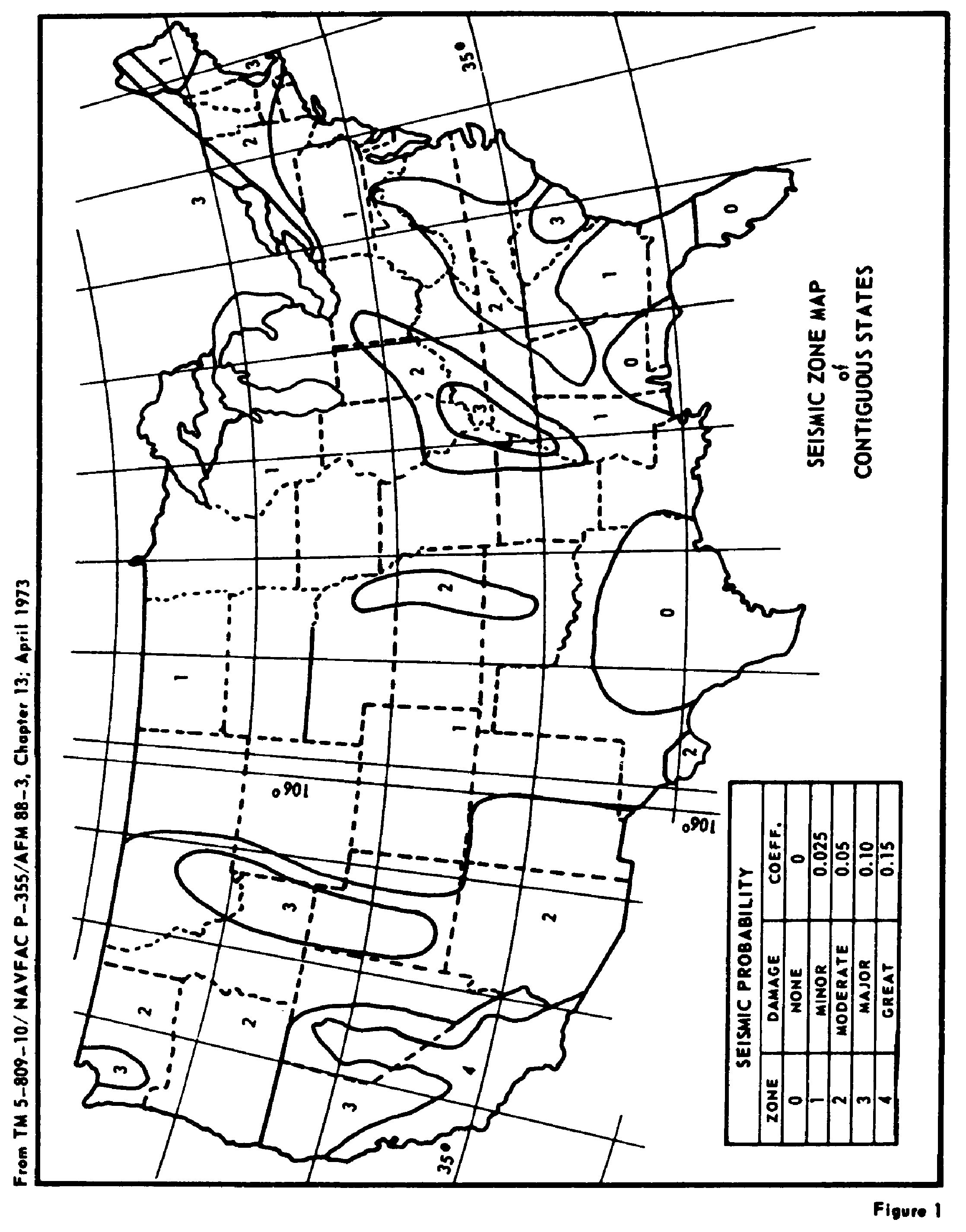
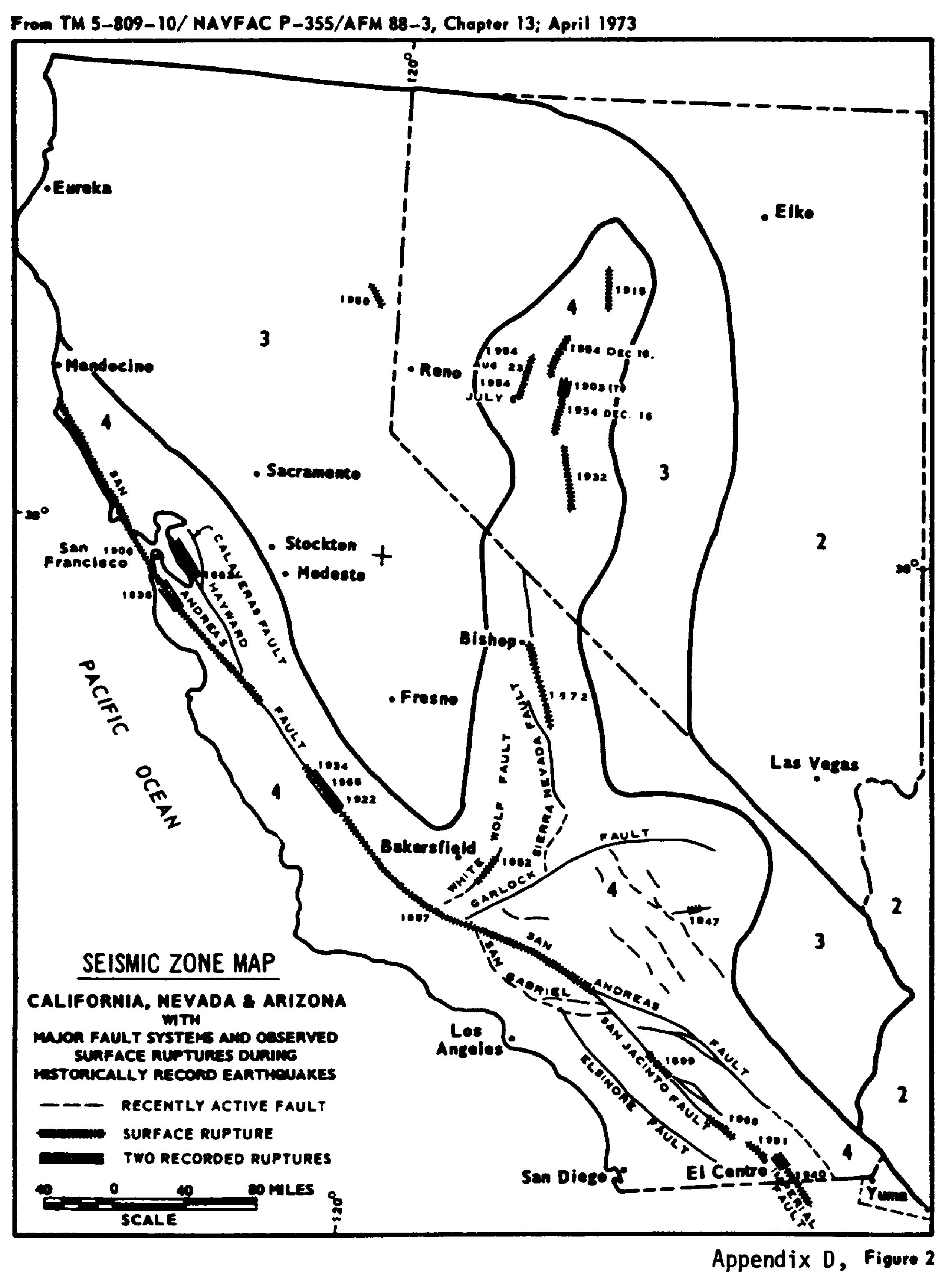
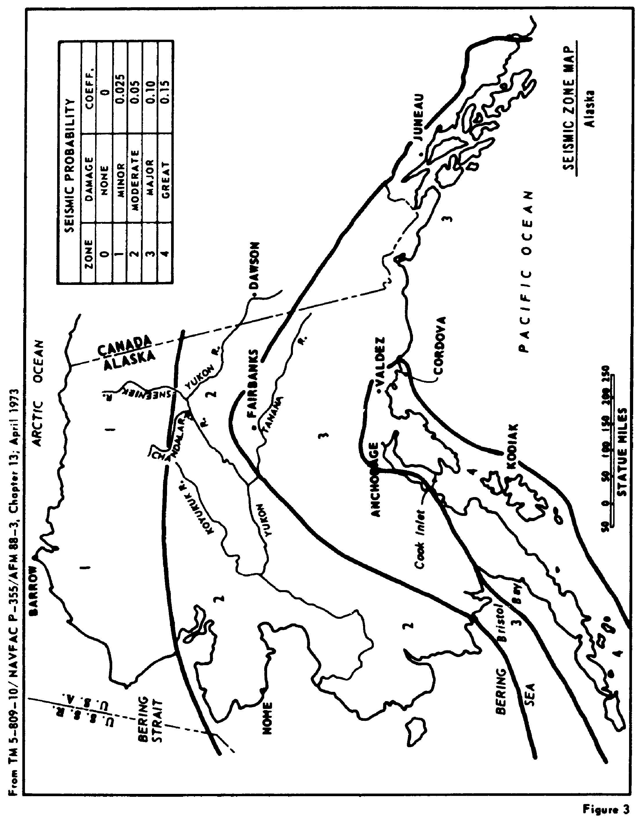
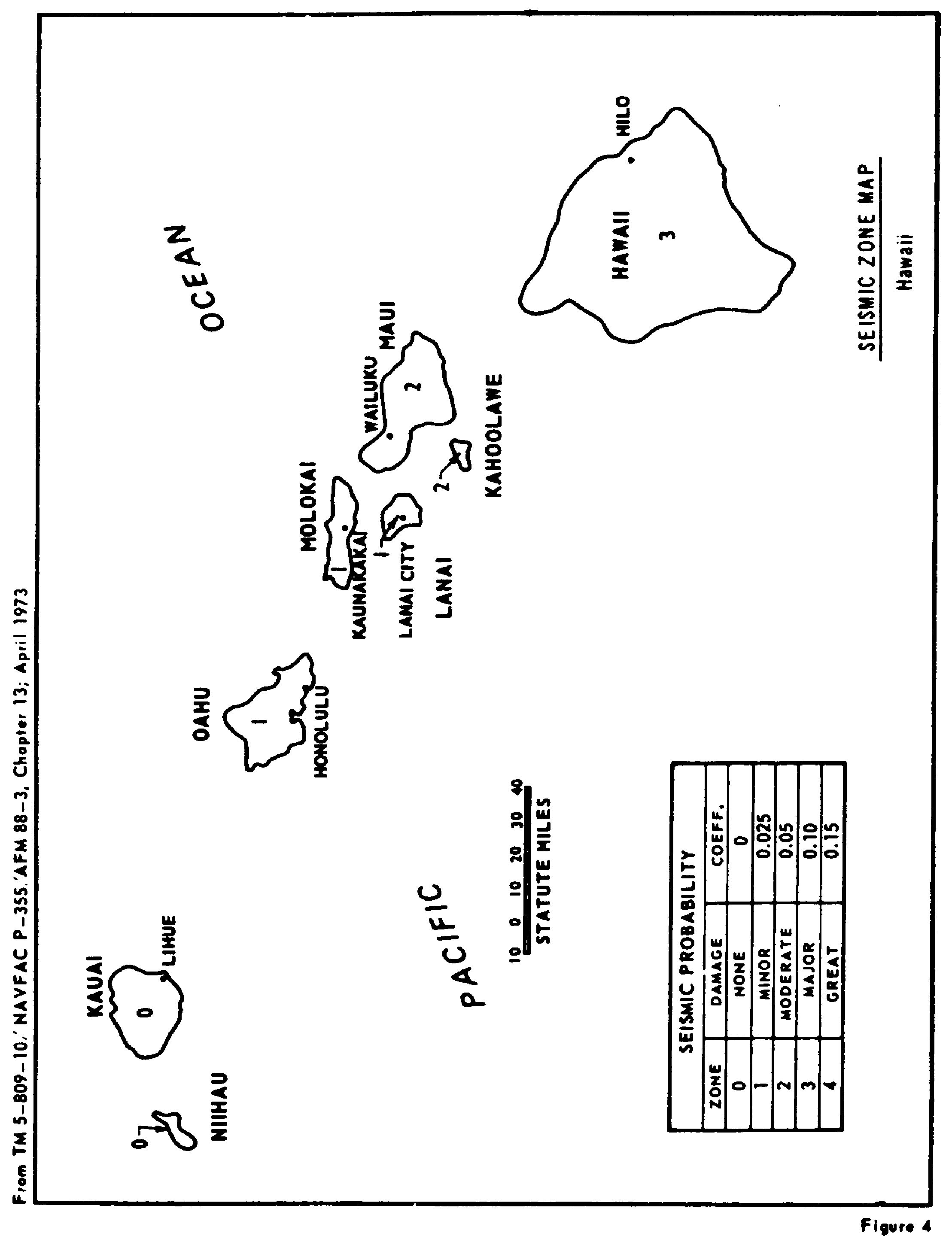
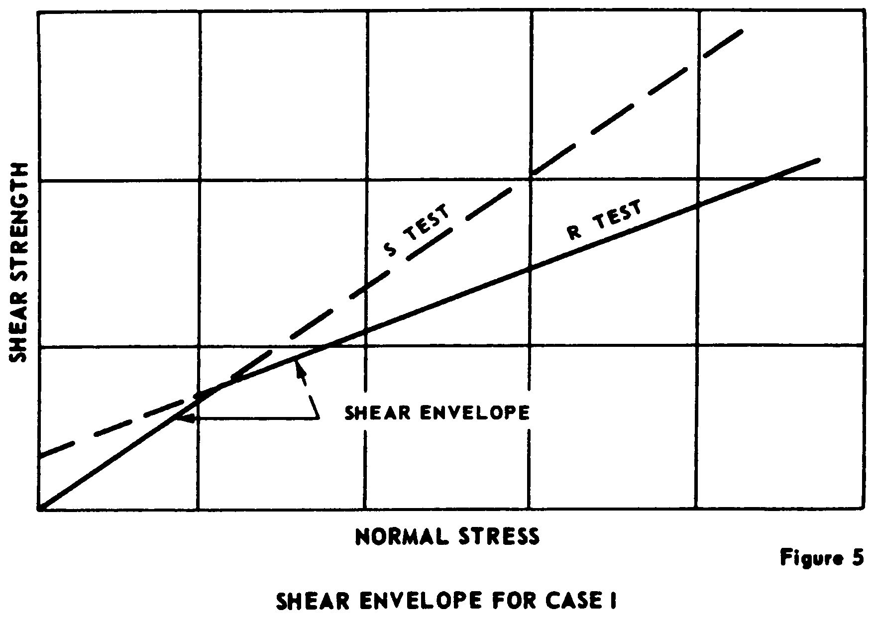
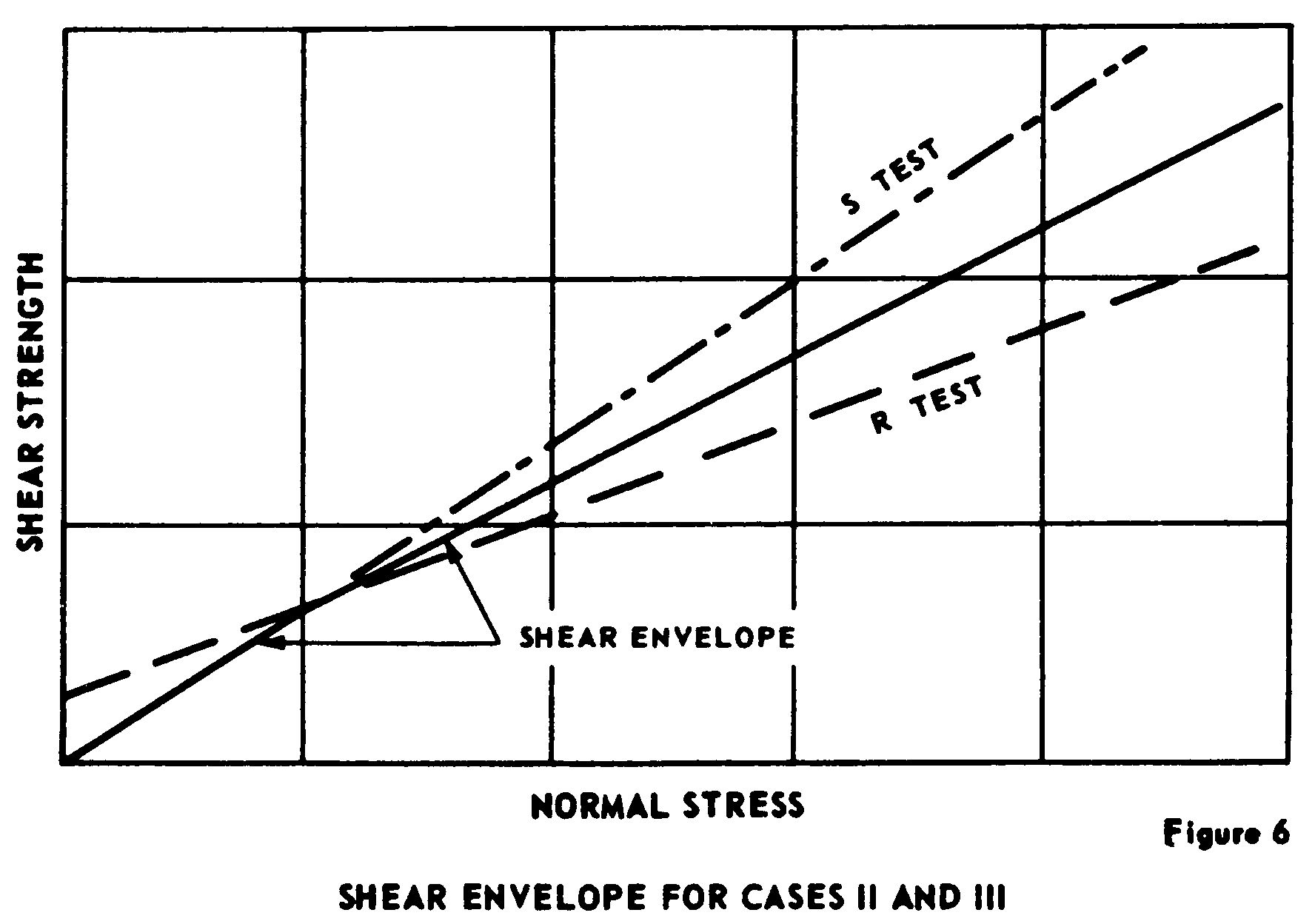
Cite this article: FindLaw.com - Code of Federal Regulations Title 33. Navigation and Navigable Waters § 33.222.6—Recommended Guidelines for Safety Inspection of Dams - last updated January 02, 2025 | https://codes.findlaw.com/cfr/title-33-navigation-and-navigable-waters/cfr-sect-33-222-6-app-d/
FindLaw Codes may not reflect the most recent version of the law in your jurisdiction. Please verify the status of the code you are researching with the state legislature before relying on it for your legal needs.
Get help with your legal needs
FindLaw’s Learn About the Law features thousands of informational articles to help you understand your options. And if you’re ready to hire an attorney, find one in your area who can help.
